All three editions of Visio 2010 include a network diagram template called Basic Network Diagram.
In this exercise, you will use that template to create a diagram of a simple corporate network.
Set Up
Start Visio, or if it’s already running, click the File tab, and then click New. In the Template Categories section, click Network, and then double-click the Basic Network Diagram thumbnail. Save the drawing as Network Diagram (Basic).
- Drag an Ethernet shape from the Network and Peripherals stencil onto the drawing page and position it a couple of gridlines in from the left edge of the page.
- Drag the resize handle on the right end of the Ethernet shape until the network segment is approximately 100 mm (4 inches) long.
Tip
Remember that the Width button on the status bar displays the current length of any selected shape, so you can use it as a guide as you drag the resize handle.
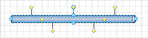

- With the Ethernet shape still selected, type Branch Office 1 to label the network segment, and then click anywhere on the background of the page.
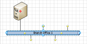
- Drag a Server shape onto the page and place it above and toward the left end of the Ethernet shape.
- Click once on the Ethernet shape to select it, and then drag any yellow control handle toward the center of the server until a red square appears around the control handle (there’s a connection point in the center of all of the computer and network shapes you will use in this exercise).Notice that the connector line remains attached to the Ethernet as you drag the control handle left or right.

Important
Because there are only seven yellow handles on the Ethernet shape, you might think that you can only connect seven devices. However, each of the two control handles in the middle of the Ethernet segment actually hides more than two dozen additional handles. In fact, the Ethernet shape can accept up to 64 connections.
- Drag a Printer shape above and toward the right end of the Ethernet, and then connect the printer to the network by dragging a yellow handle and gluing it to the printer.
- Drag two PC shapes and one Laptop computer shape from the Computers and Monitors stencil and drop them below the Ethernet shape.
- Drag a yellow control handle and glue it to the first PC.
- Repeat Step 8 with the second PC.
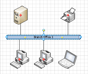
Your next task will be to connect the laptop to the network but there aren’t any more control handles below the Ethernet segment.
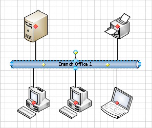
- Drag a control handle from the middle of the Ethernet shape and glue it to the laptop.As you can see in the following figure, dragging a control handle from the middle of the Ethernet segment successfully connected the laptop to the network, but there are still additional control handles available for future use.

Tip
In this graphic, there is an unused control handle/connector line just above the center of the Ethernet segment. If you don’t want it there, don’t try to delete it—you’ll end up deleting the entire Ethernet segment. Instead, if you want to hide the unused connection, drag its control handle back into the interior of the Ethernet shape. Then it won’t be visible unless the network segment is selected.
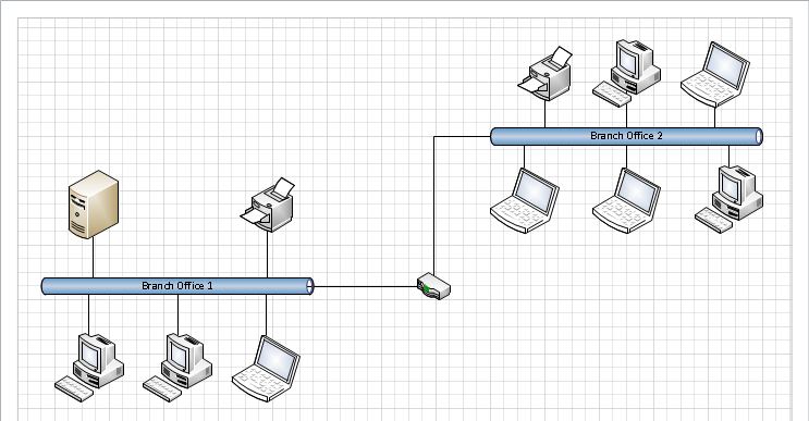
- Drag another Ethernet shape into the upper-right corner of the page, leaving enough room to add shapes above it.
- While the Ethernet shape is still selected, type Branch Office 2, and then click anywhere on the background of the page.
- Drag a Printer shape, two PC shapes, and three Laptop computer shapes, and attach them to the new network segment so you have a network that looks like the one on the right side of the graphic in Step 16.
- Drag a Router shape from the Network and Peripherals stencil into the center of the page.
- Drag the remaining unused connector from the Branch Office 1 network and glue it to the router. Notice that the connector repositions itself so the end attached to the Ethernet is closer to the router.
- Drag a connector from the Branch Office 2 network and glue it to the router.The connector bends as you drag it toward the router—it behaves more like a dynamic connector than just a line. Your finished network diagram should look something like the following graphic.