Important
The information in this section applies only to the Professional and Premium editions of Visio 2010.
You created a stylized representation of your network. To build a more complete network representation, you need to add a diagram of the network equipment rack in the data center. You will use some of the stencils from the Rack Diagram template to create that picture.
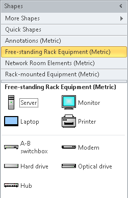
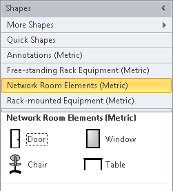
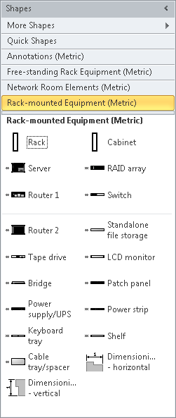
The Rack Diagram template includes four stencils, three of which contain equipment and rack shapes (the fourth contains annotation shapes). The three equipment stencils are shown side by side in the following graphic.
In this exercise, you will create the foundation for building a rack diagram by adding two stencils from the Rack Diagram template to your current drawing. You will also add a new page and will set the page attributes so you can create a drawing whose shapes are drawn to scale. Finally, you will add a rack shape to the new page.
Set Up
If you completed the preceding exercise, continue working with the Network Diagram (Organized) drawing.
- Save your drawing as Network Diagram with Rack.
- In the Shapes window, click More Shapes, point to Network, and then click Free-standing Rack Equipment.
- In the Shapes window, click More Shapes, point to Network, and then click Rack-mounted Equipment. The upper part of the Shapes window now shows the original stencils plus the two you’ve just opened.
Next you will add a page that has the dimensions and drawing scale to hold an equipment rack.
- Double-click the Page-1 name tab, type Network Overview, and then press Enter.
- Right-click the Network Overview name tab, and then click Insert.
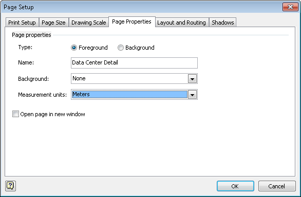
- Type Data Center Detail, click the Measurement units drop-down arrow, and then select Meters.
Tip
Changing measurement units is not required. However, a standard equipment rack is just over 2 meters (6.5 feet) tall. By selecting Meters as the measurement unit, the rulers on the left and top of the drawing page will show dimensions in meters, which is likely to be more useful than showing thousands of millimeters.
If you are working in U.S. units, select either Feet And Inches or Feet (decimal).

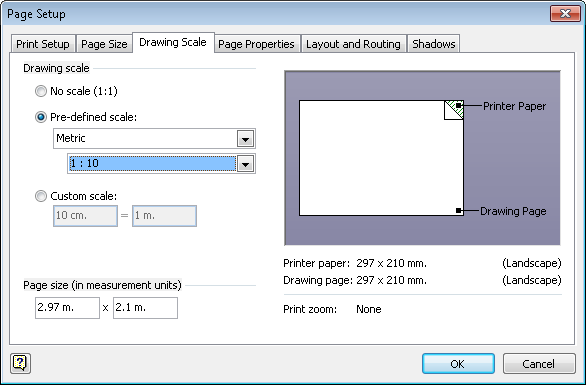
- Click the Drawing Scale tab, click Pre-defined scale, and then select Metric in the first list and 1 : 10 in the second list.
Tip
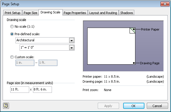
If you are working in U.S. units, select Architectural in the first list and then select 1” = 1’ 0” in the next list. See the following graphic.
Important
Visio rack shapes were created so that their size on the page reflects the drawing scale of the page. At a page-to-rack ratio of 1:1, each shape would be “life sized,” that is, each shape would take as much space on the page as the real object does in a rack. By setting the scale to 1:10, each unit of measurement in your drawing represents 10 units in the real world. For U.S. units, a ratio of 1”=1’0” means that each inch on the page represents one foot in the real world.
- Click OK.
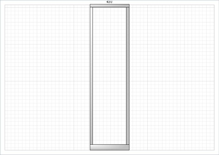
- Drag a Rack shape from the Rack-mounted Equipment stencil onto the center of the drawing page.
Because of the measurement units and page scale you’ve set in the preceding steps, the rack will occupy the entire space between the top and bottom margins of the page. (If you are using U.S. units, there will be some free space between the top and bottom margins.)

Clean Up
Save your changes to the Network Diagram with Rack drawing but leave it open if you are continuing with the next exercise.
In the next exercise, you will add equipment shapes to your rack diagram.