When you send geometry to OpenGL, it is transformed by your vertex and geometry shaders from the incoming (object) coordinate space into the clip coordinate space. This is where OpenGL performs clipping to determine which vertices lie within the viewport and which lie outside the viewport.
To do this, OpenGL divides 3D space into six half spaces defined by the bounds of the clipping volume. The half spaces are defined by what are known as the left, right, top, bottom, near, and far clip planes. As each vertex passes through the clipping stage, OpenGL calculates a signed distance of that vertex to each of the planes. The absolute value of the distance is not important—only its sign. If the signed distance to the plane is positive, the vertex lies on the inside of the plane (the side that would be visible if you were to stand in the middle of the view volume and look toward the plane). If the distance is negative, the vertex lies on the outside of the plane. If the distance value is exactly zero, then the vertex lies exactly on the plane. Now, OpenGL can tell very quickly whether a vertex lies inside or outside the view volume by simply examining the signs of the six distances to the six planes and by combining the results from several vertices can determine whether larger chunks of geometry are visible.
If all of the vertices of a single triangle lie on the outside of any single plane—that is, the distance from all of the triangle’s vertices to the same plane are negative—then that triangle is known to be entirely outside the view volume and can be trivially discarded. Similarly, if none of the distances from any of a triangle’s vertices to any plane is negative, then the triangle is entirely contained within the view volume and is therefore visible. Only when a triangle straddles one of the planes does further work need to be done. This case means that the triangle will be partially visible. Different implementations of OpenGL handle these cases in different ways. Some may break the triangle down into several smaller triangles using a clipping algorithm such as Sutherland-Hodgman. Others may simply rasterize the whole triangle and use brute force to discard fragments that end up outside the viewport.
These six planes make up an oblong shape in clip space, which appears as a box in the greater 3D space. When this is transformed to window coordinates, it may undergo a perspective transformation and become a frustum. This is what is referred to as the view frustum.
Clip Distances—Defining Your Own Custom Clip Space
In addition to the six distances to the six standard clip planes making up the view frustum, a set of additional distances is available to the application that can be written inside the vertex or geometry shader. The clip distances are available for writing in the vertex shader through the built-in variable gl_ClipDistance[], which is an array of floating-point values. The number of clip distances supported depends on your implementation of OpenGL. These distances are interpreted exactly as the built-in clip distances. If a shader writer wants to use user-defined clip distances, they should be enabled by the application by calling
glEnable(GL_CLIP_DISTANCE0 + n);
Here, n is the index of the clip distance to enable. The tokens GL_CLIP_DISTANCES1, GL_CLIP_DISTANCES2, and so on up to GL_CLIP_DISTANCES5 are usually defined in standard OpenGL header files. However, the maximum value of n is implementation defined and can be found by calling glGetIntegerv with the token GL_MAX_CLIP_DISTANCES. You can disable the user-defined clip distance by calling glDisable with the same token. If the user-defined clip distance at a particular index is not enabled, the value written to gl_Clip_Distance[] at that index is ignored.
As with the built-in clipping planes, the sign of the distance written into the gl_Clip_Distance[] array is used to determine whether a vertex is inside or outside the user-defined clipping volume. If the signs of all the distances for every vertex of a single triangle are negative, the triangle is clipped. If it is determined that the triangle may be partially visible, then the clip distances are linearly interpolated across the triangle and the visibility determination is made at each pixel. Thus, the rendered result will be a linear approximation to the per-vertex distance function evaluated by the vertex shader. This allows a vertex shader to clip geometry against an arbitrary set of planes (the distance of a point to a plane can be found with a simple dot product).
The gl_Clip_Distance[] array is also available as an input to the fragment shader. Fragments that would have a negative value in any element of gl_Clip_Distance[] are clipped away and never reach the fragment shader. However, any fragment that only has positive values in gl_Clip_Distance[] passes through the fragment shader, and this value can then be read and used by the shader for any purpose. One example use of this functionality is to fade the fragment by reducing its alpha value based as its clip distance approaches zero. This allows a large primitive clipped against a plane by the vertex shader to fade smoothly or be antialiased by the fragment shader, rather than generating a hard clipped edge.
It is important to note that if all of the vertices making up a single primitive (point, line, or triangle) are clipped against the same plane, then the whole primitive is eliminated. This seems to make sense and behaves as expected for regular polygon meshes. However, when using points and lines, you need to be careful. With points, you can render a point with a single vertex that covers multiple pixels by setting the gl_PointSize parameter to a value greater than 1.0. When gl_PointSize is large, a big point is rendered around the vertex. This means that if you have a large point that is moving slowly toward and eventually off the edge of the screen, it will suddenly disappear when the center of the point exits the view volume and the vertex representing that point is clipped. Likewise, OpenGL can render wide lines. If a line is drawn whose vertices are both outside one of the clipping planes but would otherwise be visible, nothing will be drawn. This can produce strange popping artifacts if you’re not careful.
The left, right, top, and bottom planes all correspond to real-world things—the limits of your field of view. In reality, your field of view isn’t a perfect rectangle. It’s more of an oval shape with fuzzy edges. In practice, though, a hard limit is defined by the bounds of the viewport—the edges of your monitor, for example. Likewise, the near plane roughly corresponds to your own eye plane. Anything behind the near plane is really behind you, and thus you shouldn’t be able to see it, but there isn’t really anything directly equivalent to it in the real world. What about the far plane? There just is no real-world equivalent to the far plane at all. Light travels an infinite distance unless it hits something.
OpenGL represents the depth of each fragment as a finite number, scaled between zero and one. A fragment with a depth of zero is intersecting the near plane (and would be jabbing you in the eye if it were real), and a fragment with a depth of one is at the farthest representable depth but not infinitely far away. To eliminate the far plane and draw things at any arbitrary distance, we would need to store arbitrarily large numbers in the depth buffer—something that’s not really possible. To get around this, OpenGL has the option to turn off clipping against the near and far planes and instead clamp the generated depth values to the range zero to one. This means that any geometry that protrudes behind the near plane or past the far plane will essentially be projected onto that plane.
To enable depth clamping (and simultaneously turn off clipping against the near and far planes), call
glEnable(GL_DEPTH_CLAMP);
and to disable depth clamping, call
glDisable(GL_DEPTH_CLAMP);
Of course, this only affects OpenGL’s built-in near and far plane clipping calculations. You can still use a user-defined clip distance in your vertex shader to simulate a depth plane that would actually have a depth value greater than one if you need to.
Figure 1 illustrates the effect of enabling depth clamping and drawing a primitive that intersects the near plane.
Figure 1. Effect of depth clamping on a primitive that intersects the near plane.
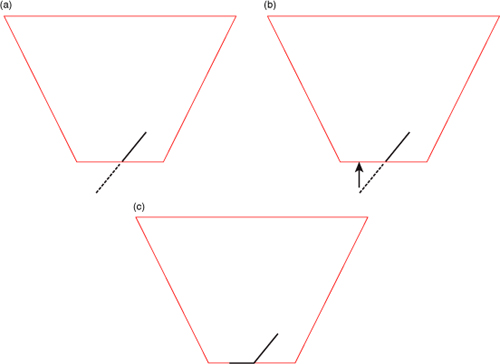
It is simpler to demonstrate this in two dimensions, so in Figure 1 (a), a the view frustum is displayed as if we are looking straight down on it. The dark line represents the primitive that would have been clipped against the near plane, and the dotted line represents the portion of the primitive that was clipped away. When depth clamping is enabled, rather than clipping the primitive, the depth values that would have been generated outside the range zero to one are clamped into that range, effectively projecting the primitive onto the near plane (or the far plane, if the primitive would have clipped that). Figure 1 (b) shows this projection. What actually gets rendered is shown in Figure 1 (c). The dark line represents the values that eventually get written into the depth buffer. Figure 2 shows how this translates to a real application.
Figure 2. The visual appearance of a clipped object with and without depth clamping.
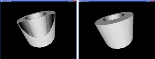
In Figure 2 (left), the geometry has become so close to the viewer that it is partially clipped against the near plane. As a result, the portions of the polygons that would have been behind the near plane are simply not drawn, and so they leave a large hole in the model. You can see right through to the other side of the model, and the image is quite visibly incorrect. In Figure 2 (right), depth clamping has been enabled. As you can see, the geometry that was lost in (left) is back and fills the hole in the object. The values in the depth buffer aren’t technically correct, but this hasn’t translated to visual anomalies, and the produced picture looks better than that in (left).