Important
The information in this section applies only to the Professional and Premium editions of Visio 2010.
In this exercise, you will use that foundation to create a detailed representation of a data center equipment rack by adding the following equipment: six servers, one PC, a router, and a power supply. In addition, you will build a “drill-down” hyperlink to the equipment rack from your stylized network drawing.
- Drag a Power supply/UPS shape from the Rack-mounted Equipment stencil and drag it toward the bottom of the rack.
The power supply shape, like all equipment shapes intended to be used within a Visio rack, is a 1-D shape. You will glue its end points to the connection points that appear on the side rails of the rack as you get close to the rack shape.
Important
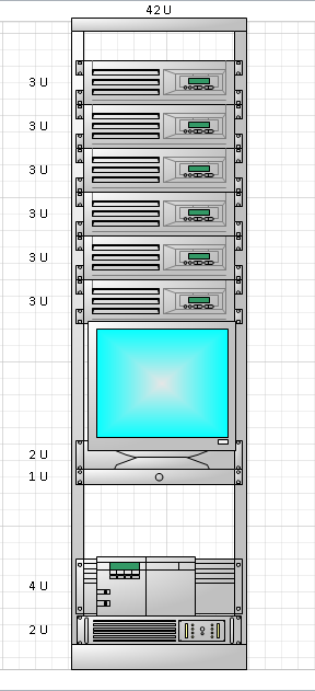
In the following graphic, you see “2U” to the left of the power supply shape. You may also have noticed “42U” above the rack shape in the last graphic in the previous exercise.
U is the abbreviation for one rack unit. Rack-mountable equipment is designed in multiples of 1U, which is 1.75 inches or 44.45 mm. Each piece of equipment you drag into the rack will display its height in U’s.
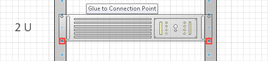
- Glue the Power supply/UPS to the connectors at the bottom of the rack.
- Drag a Server shape from the Rack-mounted Equipment stencil and drag it to the center of the rack.
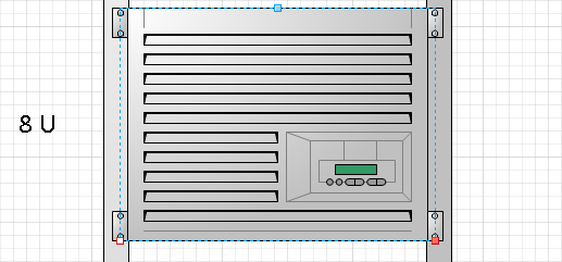

The default server shape is very large—8U—but it’s actually an interesting shape. Like many rack-mounted shapes, you can change its height, but this shape actually adjusts its appearance as you resize it; you will see this in the next step.
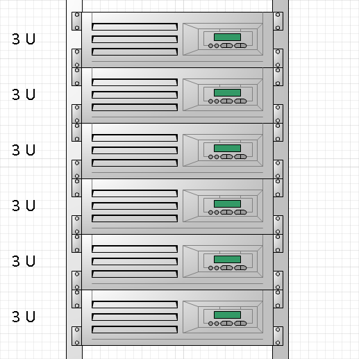
- Drag the resize handle at the top of the server shape downward until the label at the left says 3U.
Tip
As you drag the handle, notice that at 7U, 6U, and 5U, the bottom half of the shape remains unchanged as the upper half of the shape gets smaller. However, at 4U and below, the lower part of the shape begins to adjust as well. As you can see, even a seemingly simple Visio shape can have reasonably sophisticated behavior.
- Copy the 3U server shape and paste five copies onto the page. Drag each copy so it sits just above or below another server in the rack.

- Drag a Router 1 shape from the Rack-mounted Equipment stencil and position it at the bottom of the rack just above the power supply.
- Drag an LCD Monitor shape from the Rack-mounted Equipment stencil and attach it to the rack between the bottom server and the router.
This shape is not the actual monitor—that comes next—but is a shelf to hold the monitor.
- Drag a Monitor shape from the Free-standing Rack Equipment stencil and position it below the servers. Adjust the position of the shelf you dropped in the previous step, if necessary, so the monitor appears to be sitting on the shelf.
- Drag a Keyboard tray shape from the Rack-mounted Equipment stencil and attach it to the rack just below the monitor shelf. Your finished rack should look like the graphic on the left.
Tip
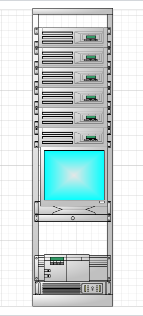
If you prefer to see the rack without the “U” dimensions, right-click on the rack or any rack-mounted shape and click Hide U Sizes. The result is shown in the graphic on the right. You can turn U sizes back on by right-clicking and selecting Show U Sizes.


At this point your rack reflects the same equipment shown in your stylized diagram on the Network Overview page. In the final steps for this exercise, you will create a “drill-down” hyperlink from the overview page to the rack.
- Return to the Network Overview page and draw a bounding box around the router and the Data Center group in the lower-right corner of the page.
- Press Ctrl+K to open the Hyperlinks dialog box.
- In the Hyperlinks dialog box, click the Browse button to the right of Sub-address. The Hyperlink dialog box opens.
- In the Hyperlink dialog box, select Data Center Detail from the Page list and select Page from the Zoom list.
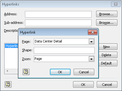

- Click OK.
- In the Description text box of the Hyperlinks dialog box, type Drill down to Data Center, and then click OK.
Important
It’s very important to understand that you’ve just applied the identical hyperlink to all selected shapes in one step. The hyperlink is not attached to the part of the page you selected with the bounding box, but is attached to each selected shape individually. Visio makes it very easy to apply the same change to multiple shapes, which is great if that’s what you want to do. However, you do need to be careful that you don’t inadvertently apply a change to multiple shapes.
- Right-click on any of the hyperlinked shapes, and then click Drilldown to Data Center.
You will see a full-page view of the rack diagram on the Data Center Detail page.
Clean Up
Save your changes to the Network Diagram with Rack diagram but leave it open if you are continuing with the next exercise.
The rack diagram you’ve created shows the key equipment in this simple data center. What might you do to enhance your rack drawing? Consider these ideas:
- Use data linking to link the equipment in your rack to a spreadsheet or database containing asset IDs, serial numbers and other inventory information.
- Link your rack equipment to a real-time or near-real-time data source so the equipment in your rack contains status information.
- Use data visualization techniques to help the user of your diagram understand the data “behind the shapes.”
- Add a patch panel and network cabling. Consider putting the cabling on a separate layer so you can easily show or hide it.
- Add data to the rack shape so its location and other information is part of your network inventory reports.
- Add hyperlinks to the rack and/or the equipment in the rack and link to photographs of the actual wiring closet or equipment.
- Change the hyperlinks on the Network Overview page so that instead of linking each server to the Data Center Detail page, you link it to a specific server shape in the rack. When you do this, try setting the hyperlink zoom level to 150% or 200%.
See Also
If you would like to see a sample network diagram that is similar to the one you’ve created in the previous several exercises but that also has several additional features, on the File tab, click New; in the Template Category section, click Sample Diagrams, and then double-click IT Asset Management.