Visio has several templates for creating block diagrams, and you can even create fairly attractive ones using just the humble Rectangle tool and a bit of formatting finesse. This section points out a few features that you might not discover on first look and points out a few graphical techniques for making your block diagrams more snazzy.
Blending Block Shapes Together
The Block Diagram template in the General template group has some nice block-and-arrow shapes for diagramming all manner of systems, architectures, flows, and anything that you can call a “block diagram.”
Whether you use the normal, flat shapes or the 3D “raised” block shapes, your diagrams will look better if you know how to blend shapes together. You can open many of the arrow and bar shapes so that they appear to blend with adjacent shapes.
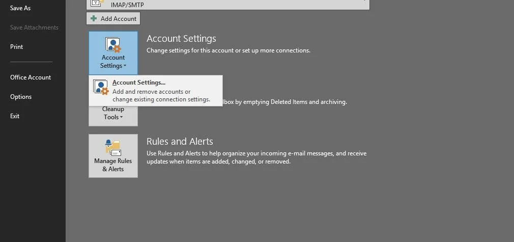
Figure 1 shows a raised block arrow’s right-click menu. Choosing Open Tail removes the line from the tail, and creates a small, filled tab that obscures the outline of the adjacent shape.
Figure 1. Right-clicking block diagram arrow shapes reveals the Open Tail item, which helps blend shapes together. Make sure that you bring the arrows to the front, though.

You need to be sure that the arrow shape is on top of the adjacent shape for this trick to work, though. This is easily accomplished by right-clicking the arrow again and choosing Bring to Front.
If you later pull the arrow away from the other shape, you can close the tail by right-clicking and choosing Close Tail.
3D Perspective Block Diagrams
The General template category contains the Block Diagram with Perspective template. The shapes in this template one-up the Blocks Raised shapes by venturing into the third dimension in a more realistic fashion. They appear to converge at infinity, which can make for some interesting diagrams.
To effectively use these shapes, you need to keep a few concepts in mind:
The purple crosshairs shape with the “V.P.” text is the vanishing point. This is the virtual “point at infinity” toward which the shapes converge. You can freely move the vanishing point around to change the perspective of the whole diagram.
The V.P. shape doesn’t print, so don’t worry about it ruining your handouts at the next meeting.
You need to be good at managing the Z-order of the shapes so that shapes don’t appear to be on top of each other. Be ready to send shapes to back or bring them to front at a moment’s notice (Ctrl+Shift+F and Ctrl+Shift+B for shortcut fans). If you move the vanishing point, you may need to change the z-order of your shapes because some may wrongly appear on top of others.
Each shape has the Shape Data field Depth. A depth of 100% means the shape will extrude all the way to the V.P. A depth of 10% means the shape is fairly shallow.
You can select multiple shapes and set their depths at the same time using the Shape Data window.
Figure 2 shows a sample Block Diagram with Perspective, including shapes with varying depths, and one Z-order mistake.
Figure 2. Use Shape Data to set the depth of perspective block shapes from 10% to 100%. The shapes on the left have 100% depth; those on the right have 10%. Note one box on the right that needs to be sent backward.

Corner Rounding and Other Tips for Architecture Block Diagrams
I see a lot of “system architecture drawings” that use boxes within boxes within boxes to show the components and structure of a system. Figure 3 shows an example that conceptualizes Visio’s bits and pieces.
Figure 3. A block diagram of Visio elements that could be improved.

Figure 3 is rather lackluster and contains graphical shortcomings that I often see. Contrast it with Figure 4, which is more attractive and easier to read.
Figure 4. Corner rounding should be large for outer shapes, but small for inner shapes so that curves appear parallel. Line weight and shading can also be used to accentuate hierarchy and structure.

Here are five tips for sprucing up system architecture block diagrams.
Corner rounding should decrease as you move further inside the diagram. The boxes look better if their borders are parallel. Decreasing corner radii as you move inward helps accomplish this.
You can use the Rectangle tool to create these blocks; you don’t have to use a shape from a stencil. The Line formatting dialog has several corner rounding choices, plus you can enter exact values yourself.
Containers are an interesting option for diagrams like this.
Drawing rectangles and snapping to the grid worked best for me. You might find this attack easier than using Containers.
Varying fill color, line weight, and font size can make the hierarchy more apparent and easier to look at.