Many of the templates in the Maps and Floor Plans group open with the Walls, Doors, and Windows stencil. This library contains shapes for drawing exterior and interior walls, and the windows and doors that perforate them.
These shapes come with extra functionality that make them easier to work with. If you are familiar with the automated features, you won’t find yourself fighting against them; you can let them do a lot of mundane work for you.
The key behaviors that you will encounter can be summed up as follows:
-
Wall, window, and door shapes are all highly configurable via right-clicking and Shape Data fields. Don’t look for hundreds of different symbols, look at the configuration options for the basic type of object.
-
Doors and windows automatically align to walls when dropped on or near them, and stay glued when walls are moved.
-
Walls automatically extend to other walls when brought within a small distance of each other.
-
Wall intersections and corners heal automatically, so you don’t have to worry about line removal.
Creating Building Plans Using Wall Shapes
|
1.
|
Start a new Office Layout drawing.
|
|
2.
|
Create a rough building outline using the Line tool. It can be any shape; have fun and go wild! But be sure to draw it in the counterclockwise direction, though.
|
|
3.
|
Leaving the outline shape selected, go to the Plan contextual Ribbon tab and click Convert to Walls. The Convert to Walls dialog appears.
|
|
4.
|
In the dialog, select Exterior Wall, check Add Dimensions, check Delete under Original Geometry; then click OK. You should see something like Figure 1.
Figure 1. A polyline created by the Line tool is converted to walls and dimension lines. By drawing the outline counterclockwise, you ensure that the dimension lines are on the outside of the space.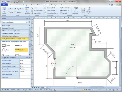 2.23.11 If you had drawn the building in the clockwise direction, the dimensions would have appeared on the inside of the building, a minor nuisance or blessing, depending on your point of view! |
|
5.
|
Explore the new shapes. Each wall segment and dimension line is a separate shape. The dimension lines are glued to the walls. If you change the length of a wall, the dimension line changes with it, and the dimension’s readout updates to show the actual length.
|
|
6.
|
Select a wall shape. Note that it has Begin and End handles as well. It too is a 1D shape.
|
|
7.
|
Note that dimension text appears on the wall when a wall shape is selected. This is a visual aid to help you keep the length of the wall in mind, but it goes away when you deselect the shape. If you need dimensions in printed output, use dimension line shapes.
|
|
8.
|
|
|
9.
|
Move the wall end back to the corner where it originally was. Notice that the black outline magically re-heals at the corner joint. You don’t see any inappropriate lines.
|
|
10.
|
View the Shape Data window for the selected wall shape and experiment with the properties. Note that some affect the look of the wall, whereas others are purely informational. These might be useful in reports or for construction details.
|
|
11.
|
Drop another Wall shape from the stencil in the middle of the outline. Notice that it doesn’t automatically come with an attached dimension line. Experiment with moving the ends close to other walls and notice how the wall automatically jumps to intersect and heal with those walls.
|
|
12.
|
Save the drawing for use in the next exercise.
|
Now that you know how to work with the supersmart wall shapes, it’s time to learn how to add windows and doors to your plan. In the next exercise, you also see how to automatically create space shapes that are great for analyzing floor area and tracking facilities.
Using Window, Door, and Space Shapes with Walls
|
1.
|
Continue working with the drawing you created in the last exercise.
|
|
2.
|
Drag a Window shape onto the plan and drop it on a wall that runs vertically. Notice that the window automatically rotates to match the orientation of the wall. Also, note the red handles on the selected window shape. These indicate that it is glued to the wall.
|
|
3.
|
Verify this glue by moving the wall onto which you dropped the window. The window moves with the wall. Undo this step to restore the integrity of your beautiful outline.
|
|
4.
|
Change the thickness of the wall using the Wall Thickness Shape Data field. The thickness of the window changes with the wall. The window is truly integrated with the wall in an intelligent way.
|
|
5.
|
Experiment with the width of the window. You can change it manually by dragging its selection handles. You can also select or enter values in the Window Width Shape Data field.
|
|
6.
|
Drop a Door shape on another wall. It auto-orients and glues to the wall. It has features, data fields, and behavior that are very similar to the window shape.
|
|
7.
|
Notice the yellow control handle on the Door. Use it to actually open and close the door! You can use the Shape Data field Door Open Percentage to open and close the door as well.
|
|
8.
|
Right-click the door and notice the Reverse Left/Right Opening and Reverse In/Out Opening options. You don’t have to rotate or flip the doors once they’re attached to walls; just use the flip features.
|
|
9.
|
Drop a Space shape in the middle of your plan. You see a cross-hatched rectangle that displays name and area. You want this shape to match the outline of your building plan and accurately reflect the area of the space.
|
|
10.
|
Right-click the Space shape and choose Auto Size. The Space shape magically morphs to fit the interior of your plan’s outline, and the area value updates. This is also shown in Figure 1.
Space shapes take ordinary floor plans into the realm of facilities management systems. If you look at the Shape Data for the Space shape, you see fields like Name, Space ID, Department, Phone Number, Occupancy, Capacity, and Zones. These can be used to tie the space to people and equipment shapes and then used in reports. If you have Pro or Premium, you can color spaces according to data using the Data Graphics feature. |
|
11.
|
Go to Home, Editing, Layers, Layer Properties to bring up the layers dialog. Notice that the shapes are pre-assigned to several useful layers like Building Envelope, Dimensions, Door, Space, Wall, and Window. These layers are great for reducing complexity and preventing modifications. For instance, while you are working on spaces, you might choose to hide the Dimensions layer and lock the Building Envelope layer so that you don’t accidentally move any walls, windows, or doors.
|
I could go on and on about Floor Plans, but I think that’s a good introduction. If you’re thirsty for more, be sure to check out the Display Options button on the Plan tab. This dialog enables you to fine-tune the overall look of your drawing; the settings apply to everything on the page.